.

Balanced Input Amplifier
Using a 12AT7 Vacuum Tube

Balanced Input Amplifier
Using a 12AT7 Vacuum Tube

The following circuit provides both a balanced and unbalanced input using a 12AT7 vacuum tube. The first 12AT7 stage is used to provide signal inverting for one side of the balanced signal input. The other balanced signal side does not use any active circuits prior to mixing the signals. The second 12AT7 stage is used to make up for lost gain and provides an unbalanced input with 10 dB more gain than the balanced input. This provides a balanced input with a 0 dB input level and an unbalanced input with a −10 dB input level.

balanced input using a 12AT7 vacuum tube

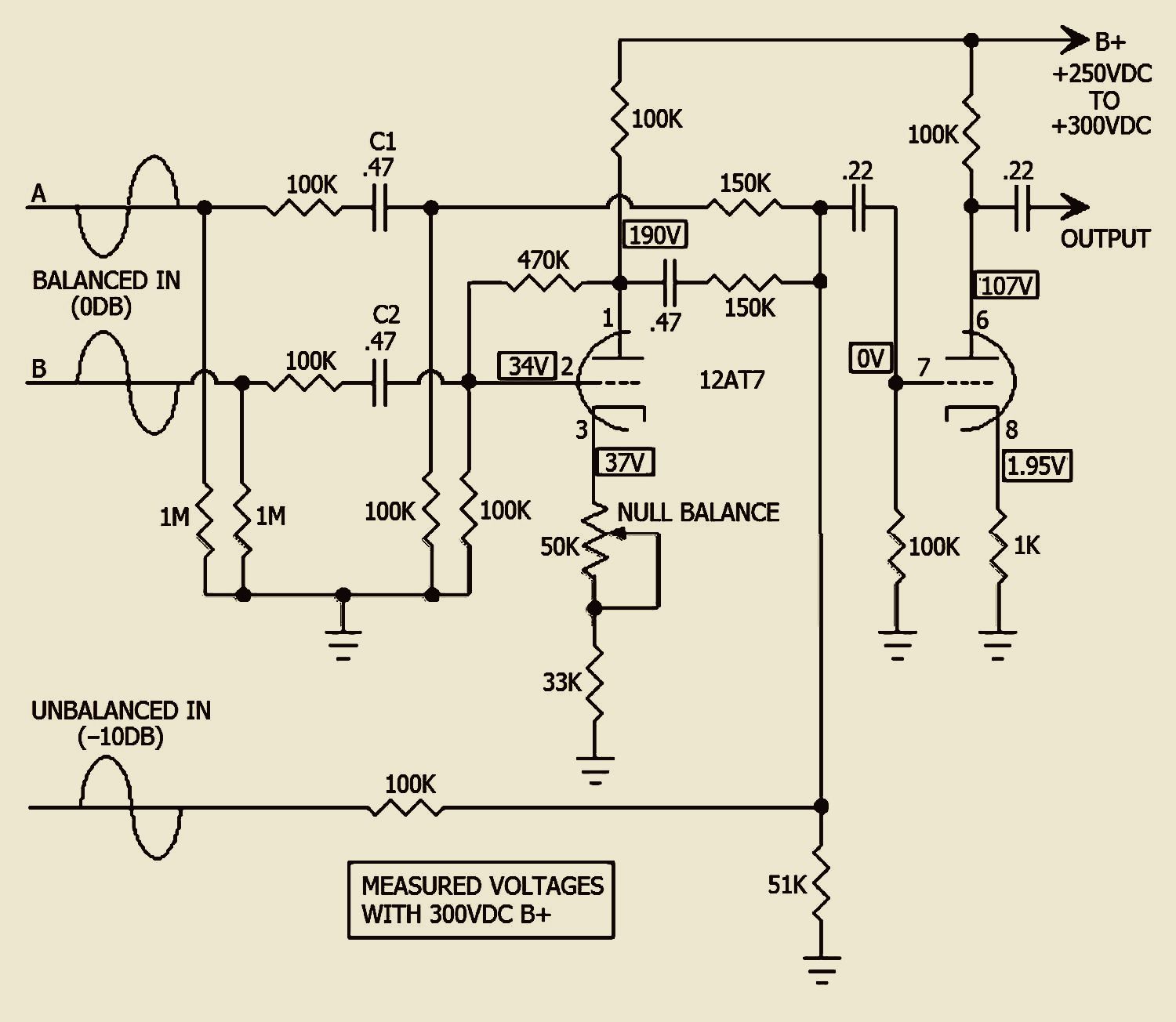
Many professional balanced inputs and outputs are low impedance. This active high impedance input is considered a bridging input. Active means the use of an amplifying stage without the use of an input transformer. Bridging refers to placing one circuit over another. High-impedance bridging inputs will work across either high or low impedance. The coupling capacitors and resistors must be the values indicated, or else common mode rejection will be less effective. The two 1M resistors on the balanced input serve to allow input capacitors to charge and equalize potential. This helps reduce the static pop when a connector is plugged into the balanced input.

Power supply requirements
High Voltage B+ Supply = +250VDC to +300VDC @ 4-mA
Filament voltage = 6.3VCT @ .3-amp
Stranded 22 AWG size wire can handle up to 7 amps of current and can be used for all wiring in this project including filament wiring.

Component List.
(Single Channel)
(1) – 12AT7
(1) – 9 pin miniature tube socket
(1) – 1K ohm resistor ½ watt 5%
(1) – 33K ohm resistor ½ watt 5%
(1) – 51K ohm resistor ½ watt 5%
(8) – 100K ohm resistor ½ watt 5%
(2) – 150K ohm resistor ½ watt 5%
(1) – 470K ohm resistor ½ watt 5%
(2) – 1M ohm resistor ½ watt 5%
(1) – 50K potentiometer linear taper
(2) – .22uF 400VDC capacitor axial leads
(3) – .47uF 400VDC capacitor axial leads
(?) – Terminal strip tie points, as needed

NOTE: To reduce hum and noise pickup, keep wiring as close as possible to the 12AT7 socket. If you would like to save some room, the .47uF input capacitors, C1 and C2, may be rated 100VDC.

ADJUSTING BALANCE NULL
Connect the two balanced signal inputs, A and B, together. Connect an unbalanced audio source between the balanced inputs (A and B tied together) and ground. The output of the second 12AT7 stage should be connected to a system so you can hear what you are doing. Power up the circuit and allow the tube to warm up for a few minutes. While playing the audio source, adjust the balance null potentiometer for minimum audio out.

The balance null may need to be touched up as the 12AT7 vacuum tube and circuit components age.

OPERATING SPECIFICATIONS
Maximum input level balanced input = +30dB.
Maximum input level unbalanced input = +30dB.
Frequency response −1dB points = 20Hz and 20KHz.
Distortion @ +10dB out = less than 1% 20Hz to 20KHz.
Maximum output level, output loaded 100K = +30dB.

NOTE: This circuit works best with a 12AT7 vacuum tube. Using higher gain tubes such as a 12AX7 will result in null balancing being more critical, and the unbalanced input sensitivity will be increased to −15 dB.

Russell O Hamm paper, tubes versus transistors Class D, Class A & Class AB Loudspeaker distortion Selecting capacitors for the best performance Amplifier damping factor Push-pull balance - W T Cocking Cathode follower output Amplifier design for tube rolling Half-watt 6SN7 headphone amplifier

Home Page

last update 07/07/2025

.