.


Class A and Class AB push-pull vacuum tube amplifiers are primarily the DIY audio circuits that I work with. I have not tested, worked with, or listened to any Class D audio amplifiers. I have avoided Class D amplifiers because of a previous experience in radio broadcasting with PDM modulation that was introduced in 1975. As the transmitters aged, the sound quality degraded, probably due to component value changes with age. The system in 1975 used 70 KHz switching. Current PDM systems use much higher switching frequencies. With the higher frequencies, PDM circuit boards are subject to effects common with RF circuits and are prone to anomalies that can degrade performance. If you follow the link below to Rod Elliott's page, you will find that Class D amplifiers are not the best DIY project to tackle.
Class D Mechanisms:
The incoming audio signal is converted into a series of very fast high-frequency on-off pulses. The pulses are all the same amplitude,
but their width determines how long they stay on and changes to match the original audio signal. The amplifier's power transistors
act like switches, rapidly turning fully on or fully off in sync with the pulses. On the output a special filter, usually made of
coils and capacitors, smooths out the rapid pulses. The high-frequency parts are removed, leaving behind the original audio waveform.
Class D amplifiers are much more efficient than Class A, capable of delivering a power output of 200 watts a channel or more
while drawing less utility power.
Considering the process of the input signal of a Class D amplifier being converted to high-frequency pulses and an output stage operating as on-off switches, I have to wonder if the high-frequency switching and simulated switched analog output are generating a potpourri of harmonics, and are any of those harmonics leaking through the output filter?
Apparently there are problems related to some Class D designs. In particular, the high switching frequency and circuit board layout. Switching frequencies above 100 KHz will be more susceptible to circuit design and circuit board layout flaws. Such high frequencies require engineering similar to RF transmitter design with careful attention to circuit layout. You can read Rod Elliott's page on the subject. Rod has done extensive testing of PDM topology. More detailed technical information on Class D amplifiers can be found on the Analog Devices website.
Class A Mechanisms:
Class A amplifiers provide linearity and low signal distortion, are simple and stable, and provide very good signal reproduction.
For the DIY builder, Class A circuits are easy to work with.
In 2020 I became interested in low-power audio based on the notion that one should not have ear-damaging power in an audio system. That is, of course, assuming one values keeping their hearing in prime condition for years to come. For low-power systems, Class A amplifiers are a good match. At lower power levels, relatively speaking, the low efficiency of Class A is not a big issue.
Class AB Push-Pull:
Besides being more efficient than Class A, there is an advantage in that the current flows in opposite directions through the output
transformer. If the currents are equal, they will cancel out standing current in the transformer, resulting in no lamination air gap
being required. Any imbalance from the phase inversion to the output transformer secondary will result in some anomalies occurring,
possibly unbalancing currents through the output transformer primary. Currents must be balanced in both halves of the primary winding,
or else standing current will rise, increasing distortion, especially in the low-frequency range. In addition, if the push-pull output
is not properly biased, crossover distortion can be a problem.


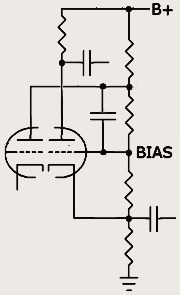
The phase inversion circuit, as shown, is used for the 30-watt monoblock amplifier in my book. It has a special bias arrangement to set the phase inversion balanced. As with a typical split triode circuit, the phase inverter connects directly to the output tubes through coupling capacitors. As long as the output tubes are matched, there should be no imbalance.
Some high-power push-pull amplifier circuits may use voltage amplifiers after the phase inversion in order to have enough undistorted signal drive to the output tubes. Any voltage amplifier stages after the phase inversion must maintain balance to the output tubes. Class A being linear does not suffer from balance problems or crossover distortion.
Russell O Hamm paper, tubes versus transistors Loudspeaker distortion Selecting capacitors for the best performance Amplifier damping factor Push-pull balance - W T Cocking Cathode follower output Amplifier design for tube rolling 12AT7 Balanced input Half-watt 6SN7 headphone amplifier
last update 07/15/2025
.