Vacuum tubes are high-impedance devices. This can be a problem when connecting a pre-amplifier device, such as an audio control
or mixer unit, to a power amplifier or other device. If you use the plate output of a stage to couple through a cable, the
capacitance of the cable can cause a substantial loss of higher frequencies.
One solution is to use a step-down matching transformer to convert the high plate impedance to a low impedance. There are two
problems with using a transformer: high-quality transformers tend to be expensive, and there is a loss of signal level when
converting from high to low impedance with a step-down transformer. A more practical solution is to use a cathode follower
output. The cathode follower has a high-impedance grid input and a low-impedance cathode output. A cathode follower has low
noise and distortion, as well as a wide frequency response, but no gain.
The cathode follower does have some limitations. It is intended for cables up to about ten feet in length. Anything significantly
longer will require a lower output load impedance. Professional equipment commonly uses a 600-ohm load impedance, plus the lines
are balanced for low-noise pickup over long cable lengths.
USING A 6SN7
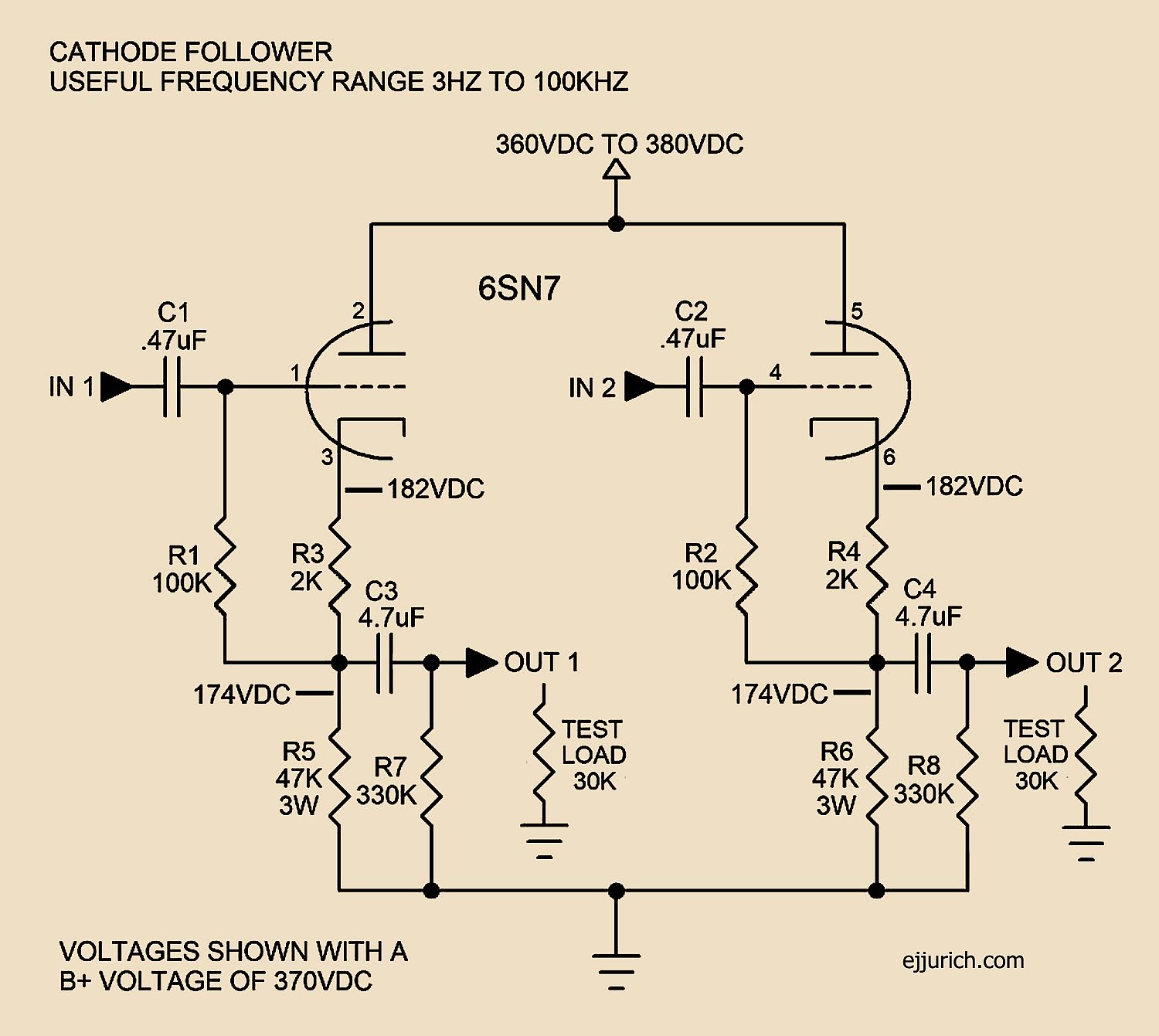
In the circuit below, resistors R7 and R8 allow C3 and C4 to charge without any connection at the output. This prevents a loud
pop when plugging connectors into the output jacks. To avoid low-frequency roll-off or phase shift, the values of C3 and C4
must be at least
4.7 uF. C3 and C4 should be film-type capacitors, rated at
250 VDC or higher. Do not use electrolytic-type capacitors for C3 or C4.
In this case, the tube is operating at 182 volts above ground. With the tube operating at 182 volts above ground, you cannot
simply multiply plate voltage by plate current to calculate plate dissipation. Only voltage across the tube is used. Voltage
across the tube is the B+ supply voltage minus the voltage at the cathode. Dissipation is then
Calculate current flow each tube section
(using cathode current)
Voltage across each cathode resistor
182 VDC
Current through each cathode resistor
I = E/R, 182/47,000 = 0.004 amps
Voltage across each tube section
370 - 182 = 188 volts
Plate dissipation each plate
Watts = E X I
188 X 0.004 = 0.752 watts
TEST MEASUREMENTS
EACH SECTION
B+ Supply = 370VDC
Plate Current 4mA
Plate Dissipation 0.752W
30K Ohm Load
Max Out Level 40V RMS
FREQUENCY RESPONSE
±0.2db 20HZ to 100KHZ
−1.0db at 3HZ
DISTORTION
(8V RMS Output)
20HZ 0.11%
50HZ 0.10%
100HZ 0.11%
250HZ 0.15%
500HZ 0.16%
1KHZ 0.15%
2KHZ 0.13%
4KHZ 0.12%
6KHZ 0.12%
8KHZ 0.13%
10KHZ 0.12%
12KHZ 0.12%
14KHZ 0.11%
16KHZ 0.11%
18KHZ 0.11%
20KHZ 0.11%
30KHZ 0.10%
40KHZ 0.10%
50KHZ 0.12%
100KHZ 0.48%
USING A 12BH7
The circuit is the same except cathode resistors R3 and R4 are changed to 2.7K to properly bias the 12BH7 grid. In this case, the tube
is operating at 183 volts above ground. Plate dissipation is calculated to be
0.748 watts.
TEST MEASUREMENTS
EACH SECTION
B+ Supply = 370VDC
Plate Current 4mA
Plate Dissipation 0.748W
30K Ohm Load
Max Out Level 40V RMS
FREQUENCY RESPONSE
±0.2db 20HZ to 100KHZ
−1.0db at 3HZ
DISTORTION
(8V RMS Output)
20HZ 0.13%
50HZ 0.12%
100HZ 0.13%
250HZ 0.17%
500HZ 0.17%
1KHZ 0.16%
2KHZ 0.14%
4KHZ 0.13%
6KHZ 0.13%
8KHZ 0.14%
10KHZ 0.14%
12KHZ 0.13%
14KHZ 0.13%
16KHZ 0.13%
18KHZ 0.12%
20KHZ 0.12%
30KHZ 0.12%
40KHZ 0.13%
50KHZ 0.15%
100KHZ 0.70%
Measurements made using Heath IG-18 generator and HP 331A analyzer
Tubes used for test measurements, 6SN7-electro-harmonix, 12BH7-JJ Electronics


