DIY Vacuum Tube Amplifiers
Website of EJ Jurich
Measuring Amplifier Damping Factor
The following procedure requires a digital AC meter that reads in true RMS values. However, meters that read at average AC values (a digital multimeter, for instance) can be fairly accurate as long as the AC signal is low distortion and a lower frequency such as 100 Hz.
For the safety of the amplifier under test, measurements should be taken at a power output level of about 1−watt. This should be a safe level for most amplifiers, solid state or vacuum tubes. For low-power amplifiers, testing with a lower power output test level may be prudent.
Required Resources
The following is required to perform measurements. An AC digital meter as mentioned. A low distortion 100 Hz signal
source. And, an 8−ohm power load resistor measured with a digital ohm meter to find its actual resistance.
Finding The Source Impedance:
→Connect a 100 Hz test signal to the amplifier input. There should be no load connected to the amplifier speaker
output.
→With a digital AC meter connected across the amplifier's speaker output, and the amplifier's input level at minimum
volume, turn on the amplifier and allow a suitable warm-up time. Increase the input volume level until the AC meter reads
about 3.0 volts and write down the exact voltage reading on paper.
→Without making any adjustments, with the AC volt meter still connected to the amplifier output, connect the
8−ohm load resistor across the speaker output along with the AC voltmeter. Write down the exact AC voltage reading
on paper.
→Subtract the loaded AC voltage reading from the no-load AC voltage reading. Then divide the result by the loaded
AC voltage reading.
→Using the actual measured resistance of the 8−ohm load resistor, multiply the value from the previous
calculation by the measured value of the load resistor.
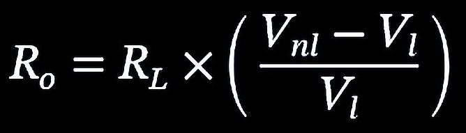
For instance, if the load resistor measures 8.1 ohms, and the no-load AC value is 3.1 volts, with a loaded AC voltage value of 3.0 volts, then the source impedance would be 0.27 ohms.
The Damping Factor is the load resistance divided by the source impedance. In this example, 8.1 / 0.27 = 30.
The source impedance is also known as the output impedance.
How Much Damping?
Source: Dick Pierce Paper
Date: 1998-2002
The process of amplifier damping is explained with analysis on levels of damping factor. The following are brief excerpts from the paper. Mr. Pierce's area of expertise was in professional audio development.
In his introduction, Mr. Pierce states that much ballyhoo surrounds the concept of "damping factor." It's been suggested that it accounts for the alleged "dramatic differences" in sound between tube and solid-state amplifiers. Also, many of the claims made, especially for the need for triple-digit damping factors, are not based in any reality, be it theoretical, engineering, or acoustical.
What is the damping factor? Simply stated, it is the ratio between the nominal load impedance (typically 8 ohms) and the source impedance of the amplifier. Note that all modern amplifiers (with some rare exceptions) are, essentially, voltage sources whose output impedance is very low. That means their output voltage is independent over a wide range of load impedance.
Mr. Pierce ran an analysis of the effects of amplifier damping factor on the decay time and frequency-dependent response of a closed-box, acoustic suspension loudspeaker system. The results were that any damping factor over 10 resulted in inaudible differences.
Comment:
Speaker cables add resistance that lowers the 'system' damping factor at the amplifier speaker terminals, effectively
rendering ultra-high amplifier damping specs moot. Thick cables with more copper allow more damping than thin cables.
Regardless of speaker cable wire gauge size, cables should be as short as possible. Low power audio systems used in
small listening areas have the advantage of short speaker cable lengths.
The paper written by Mr. Pierce is technical, detailed, and contains related formulas. The paper may be hard to follow. If
interested, a PDF of the original paper is available
here.
EJ Jurich
DISCLAIMER
Any circuits or project information presented on ejjurich.com has been tested for safe operation. Vacuum tubes get hot. Amplifiers with exposed vacuum tubes should be operated out of reach of children. Project assembly usually involves fabrication with tools and the use of a hot soldering iron. It is up to the project builder to insure the safety of everyone involved, including curious onlookers. EJ Jurich and ejjurich.com assumes no responsibility for damage, injury or otherwise related to any use of information on this site or given by other means. Many electronic circuits, in particular vacuum tube circuits, operate with dangerous voltage and current. Always exercise care when working with electronic circuits.