
Class-A 6SN7 Stereo Amplifier
Class-A 6SN7 Stereo Amplifier
Project Progress
This project is a four-watt-per-channel stereo amplifier using two 6SN7s in each channel as output tubes. The 6SN7 is known for its
full-bodied, rich sound.
Two 6SN7s paired in parallel can deliver up to four watts of Class-A sound comparable to more expensive triode output tubes.
Triodes are good for home-built amplifier projects. In particular, as Class A single-ended operation. Class A single-ended amplifiers are straightforward and simple to build. Although this project is using two output tubes, each with two enclosed triodes, the triodes are all connected together in parallel and can be considered as a single-ended output.
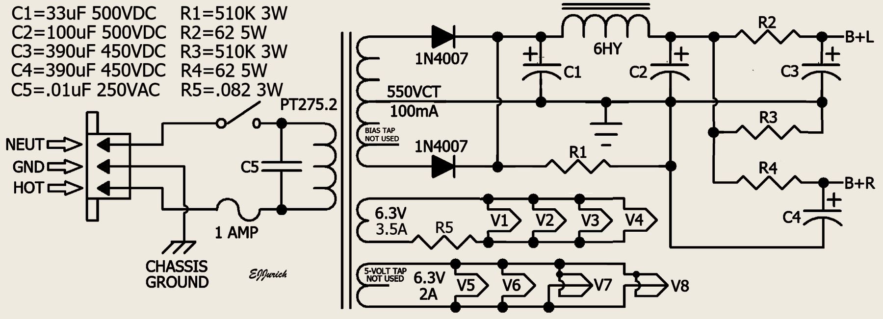
Finding transformers for a project like this can be a challenge. The power and output transformers were purchased from Musical Power Supplies in Columbia, Tennessee. The PT275.2 power transformer has two 6.3-volt windings, one with a 5-volt at 2-amp tap. The high-voltage secondary has a 55-volt bias tap.
The output transformers have dual primary impedance taps of 5,000 ohms and 7,000 ohms. The secondary taps are 0, 4, 8, and 16 ohms. Using different output taps, the primary impedance can be set to different values. Amplifier output would be 8 ohms regardless of which output tap is used.

Circuit updated 09/06/2025

Circuit updated 09/06/2025
The circuit above is the power supply for this project. The filament load is divided between the two transformer filament windings. The filament winding rated at 3.5 amps has V1, V2, V3, and V4, the four output tubes with a total load of 2.4 amps, 4-6SN7 at .6 amps each. With the 3.5 amp winding only loaded at 2.4 amps, to set the filament voltage closer to 6.3 volts, it will be necessary to add a little resistance in series with the filament line. The filament winding rated at 2 amps has V5, V6, V7, and V8; 2-6SN7 at .6 amps each, with a total load of 1.2 amps. If necessary, some resistance will be added later depending on the actual voltage with a 1.2 amp load.


A good option for using radial-type capacitors are these small ¾-inch capacitor clamps from justradios.com. Planning ahead to a time when the capacitors may need to be replaced, it is important that the clamp screw heads are easily accessible. The four capacitor clamps, two large and two small, all have the clamp screw heads facing up.
Load Resistance:
Vacuum tubes used in a power output stage exhibit a resistive source and are not inductive. The output transformer is inductive. This
relationship between an inductive load placed on a resistive source must be considered when determining a load resistance. The load
resistance is the value of the load placed on the plate of a vacuum tube.
The most common type of speaker system is the box and cone, a speaker or speakers mounted in a box enclosure. Speakers are inductive, and as such, their impedance varies depending on frequency. Their impedance can swing up and down along with an audio signal, with the lowest impedance generally at lower frequencies. This impedance swing is reflected back to the vacuum tube through the output transformer. This results in the load placed upon the vacuum tube to follow the impedance changes of the speaker. The load resistance placed on the vacuum tube must be such as to not load the vacuum tube down into distortion.
Normally, the plate resistance is first found, and then the load resistance is determined. As stated in old RCA technical manuals, plate resistance of an electron tube is the resistance of the path between cathode and plate to the flow of alternating current. It is the quotient of a small change in plate voltage divided by a corresponding change in plate current and is expressed in ohms. The example given in the RCA manual is a change of 0.1 mA (0.0001 amp) produced by a 1-volt change of plate current. With such a small value of change, a regulated constant high-voltage source is required to get accurate measurements.
An alternative method to determine plate load resistance will be used based on maximum plate dissipation values of a resistive DC load. For plate current measurements a 100-ohm plate load resistor is used. 100 ohms is close to the DC resistance of many output transformer primary windings. The value of the plate load resistor, along with the correct value of the cathode resistor, should provide a DC plate current close to what the operating current of the output stage will be.
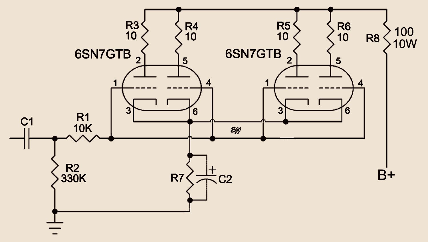
Figure 1

Figure 1 is the output circuit using a 100-ohm, 10-watt resistor, R8, as a plate load. Both tubes have all the triode sections wired in parallel. Bias is cathode bias using cathode resistor R7; current through the output circuit is determined by measuring the voltage across R7. Resistors R1, R3, R4, R5, and R6 serve to reduce instabilities such as oscillation. R2 is the grid leak resistor for all the triode sections. C2 is a 220 uF electrolytic capacitor rated at 40 volts DC. C1 is .33 uf or .47 uf rated at 400 volts DC.
Using the vacuum tube's maximum plate dissipation rating as a guide, a value is determined for the R7 cathode resistor. Using this process does not require knowing the plate resistance. Instead, voltage as measured across the R7 cathode resistor and voltage measured across the vacuum tube from plate to cathode are used to calculate plate dissipation.
Calculate Current:
With the output stage wired up as shown in Figure 1, different values of R7 resistance are temporarily connected with clip leads.
The circuit is powered up, and voltage across R7 is measured. Current through the vacuum tube and R7 is calculated using
With both sections of the 6SN7 operating, the 6SN7 datasheet states maximum plate dissipation as 5 watts per plate. Plate
dissipation is calculated using
An R7 value of 150 ohms was found to produce a good plate dissipation value. With 150 ohms and no input signal, the voltage across R7 measured 8.85 volts DC, while the voltage across the tube measured 316 volts DC.
Plate current as measured across R7,
With no input signal, I = E/R = 8.85/150 = 0.059 amps (59 mA).
(0.059/4) = 0.01475 amps (14.75 mA) per plate.
Plate dissipation,
P = E X I = 316 X .01475 = 4.66 watts.
At this point we have a reference plate dissipation near but not over the maximum allowed value. The next step is to verify the R7 cathode resistor value.
Figure 2

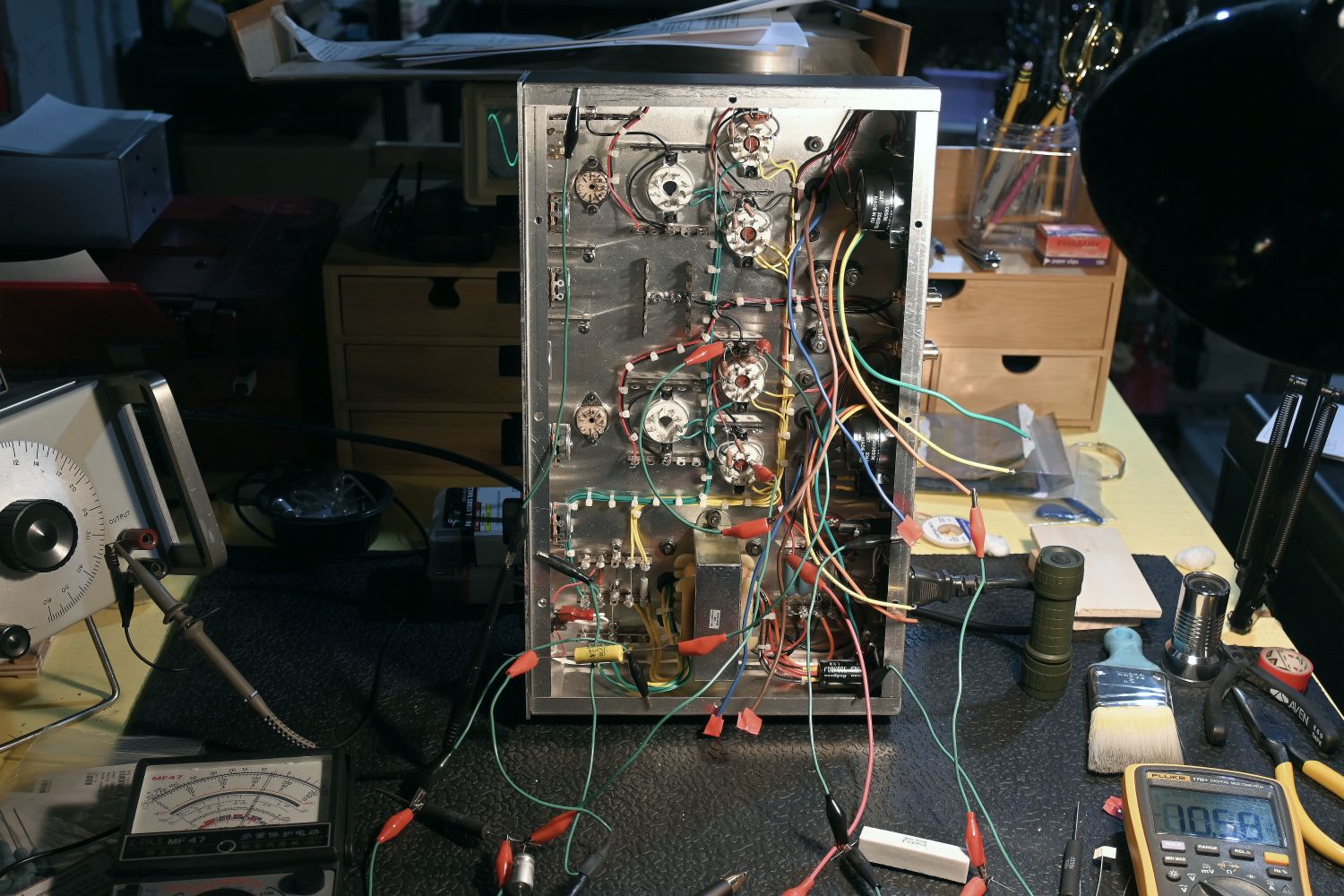
Figure 2 is the output circuit under test. At this stage the output transformers are in the circuit using clip leads. The cathode resistor R7, along with a 200 uF cathode bypass capacitor, is also in the circuit. An 8-ohm 10-watt resistor is used as a load on the output transformer secondary for all tests. The analog meter to the left monitors the high voltage supply. A digital meter is used for all measurements. The test signal is provided by a Heath IG-18 generator. The output waveform is viewed on an oscilloscope. The output signal RMS voltage across the 8-ohm load resistor is measured using an HP 331 analyzer.
I do not use computer test software. There is no technical reason not to. I like having the physical test equipment in my work area. This leaves the computer free to search for information. I find it awkward having test software on the computer and then having to click between tabs.
Looking at the results below, it seems that with the present high voltage supply power output at best is three watts.
The following measurements were taken
1 kHz signal input
Maximum output signal just below clipping
5K output transformer primary
8-ohm load resistor (all taps)
150-ohm R7 cathode resistor
8-ohm tap - 4.3V
4-ohm tap - 3.4V
16-ohm tap - 4.2V
200-ohm R7 cathode resistor
8-ohm tap - 5.0V (3 watts)
4-ohm tap - 4.0V
16-ohm tap - 4.8V
330-ohm R7 cathode resistor
8-ohm tap - 4.0V
4-ohm tap - 3.5V
16-ohm tap - 5.0V (3 watts)
7K output transformer primary
8-ohm load resistor (all taps)
150-ohm R7 cathode resistor
8-ohm tap - 4.5V
4-ohm tap - 3.6V
16-ohm tap - 4.0V
200-ohm R7 cathode resistor
8-ohm tap - 4.5V
4-ohm tap - 3.6V
16-ohm tap - 3.8V
330-ohm R7 cathode resistor
8-ohm tap - 4.4V
4-ohm tap - 3.6V
16-ohm tap - 4.4V
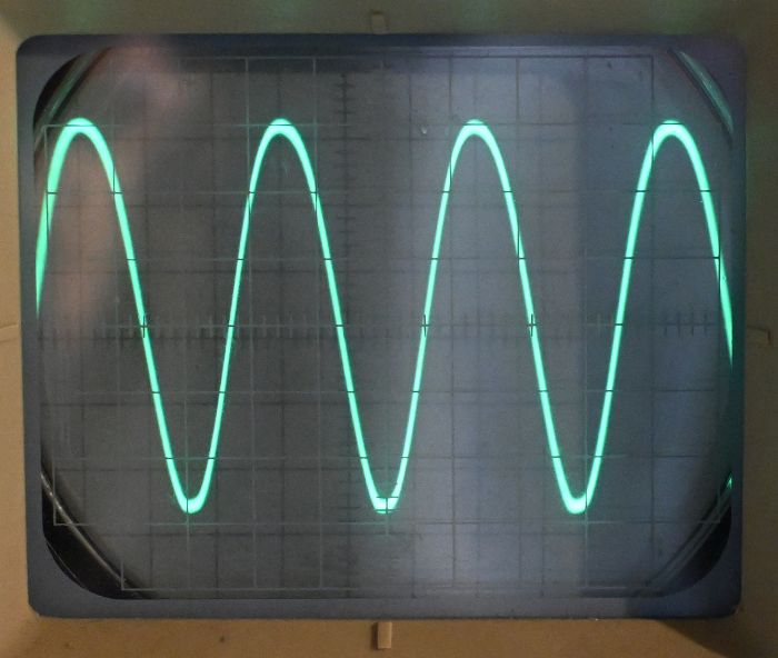
scope 1 kHz 3 watts out

scope 100 Hz 3 watts out
The distortion at 100 Hz should smooth out when the driver stage is integrated with the output stage. For now only the output stage is wired.
The best match for an 8-ohm load appears to be with an R7 cathode resistance of 200 ohms and the 5K output transformer primary. During the test above, high voltage was +340 VDC with +327 volts across the plate and cathode. Voltage at the cathode was 10.26 volts. For the sake of tweaking values, I'll order a couple additional resistor values to test in the cathode.
Plate dissipation works out to 4.35 watts. There is some room left for a bit more high voltage. After the amplifier is completely wired, we will see what voltage is needed. It may be that the output power limit is closer to 3.5 watts.
Datasheets for the 6SN7 do not specify a load resistance. Because I experimented with this same circuit a few years ago, I knew the load resistance was in the 3K ohms to 5K ohms range. The output transformers have a dual primary impedance of 5K and 7K ohms. Secondary taps are 0, 4, 8, and 16 ohms.
The output impedance load will be considered 8 ohms regardless of which output tap is used. The secondary taps can be used to double or halve the primary load impedance. For example, an 8-ohm load on a 4-ohm output tap will lower the primary impedance by half. The transformer reflects the load impedance back to the primary. If the 8-ohm load resistance is connected to the 16-ohm output tap, the primary impedance will increase by double. This provides several plate load impedance possibilities. The final load impedance will be determined after the driver stage is integrated with the output stage.