This is the home page for EJ Jurich, author of Vacuum Tube Amplifier Basics.
Vacuum Tube Amplifier Basics Second Edition
This second edition of the book has much of the original book with the addition of a more detailed example of designing and
building a vacuum tube amplifier. There are 110 concise reference pages covering technical information that pertain to vacuum
tube circuits. Includes Ohm's law, voltage, current, power, and watts. Explains capacitors, series circuits, parallel circuits,
voltage dividers, reading circuit drawings, plus other related information. Principles of vacuum tube operation and power
output are explained. Also includes the functions of grids, the effect of tube capacitance, tube resistance, heat dissipation,
bias, and calculating voltage gain. Vacuum tube and solid-state power supply design is included. The amplifier design example
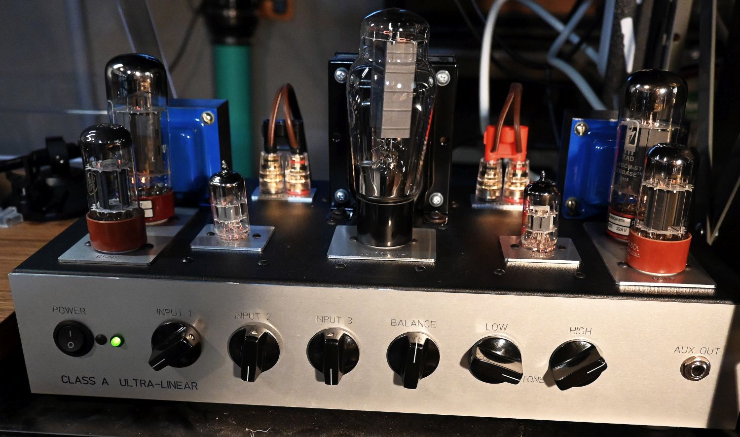
takes you through the steps of fabricating a traditional chassis layout and designing a Class A stereo amplifier (pictured on
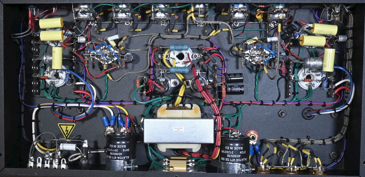
the book cover). Calculating circuit component values is presented with examples. High-resolution images illustrate
point-to-point wiring. Working with electronics and vacuum tube circuits requires some math. Circuit calculations in this book
use various forms of addition, subtraction, multiplication, and division. Formulas are all solvable using a standard 12-digit
calculator (requires a square root key). Project circuits with layout drawings include a line amplifier with 25 dB gain, a
turntable preamplifier, a 6V6/6L6 Class A monoblock amplifier, a 30-watt monoblock amplifier, and a basic 5-watt guitar
amplifier. The 30-watt monoblock amplifier is designed for tube rolling. Book Sample PDF
Format: PDF Document/eBook
ISBN: 979-8-218-61168-2
File size: 30 MB
Price: $12.00 USWho is EJ Jurich?
PayPal Checkout
After payment you will receive a link in your email to download the file
Why PDF?
PDF documents are readable on just about any device. Unlike standard eBook reflowable formats, content remains static.
For technical documents, maintaining a static layout is best.
Vacuum Tube Amplifier Basics Second Edition
available on CD
Vacuum Tube Amplifier Basics Second Edition
available on CD
Vacuum Tube Amplifier Basics, second edition, is available on CD. This may be a good option for folks that have a CD drive.
Being a physical CD, it must be mailed and is only available for purchase in the US.
Format: PDF eBook on CD
Price: $15.00
DiyAudio forums post of an amplifier build of the 30-watt monoblock project from the original book and still included in
the second edition. You might consider registering with the DiyAudio forums. It is an excellent source of information where
you can post questions.
Current Project
In 2020, I experimented with using two 6SN7s as output tubes. The four plates were connected in parallel for Class A
operation. Fixed bias was adjusted while observing a 1 KHz sine wave. The B+ voltage was 450 VDC with a total plate current
of about 40 mA. An output transformer with a primary impedance (resistance) of 3,000 ohms was used. Using plate voltage
and plate current comparisons, plate resistance was about 1,250 ohms. Operational tests were made with both a 3,000-ohm
primary and a 3,500-ohm primary output transformer. Performance was the same with either transformer. Output voltage before
waveform distortion into an eight-ohm load resistor was 6.2 volts. This works out to about 4.8 watts.
Overload Test
At 4.8 watts, B+ voltage was 440 volts with a total plate current of 50 mA. This is, of course, pushing a pair of 6SN7s
a bit beyond maximum plate dissipation ratings. Using pairs of two different brand tubes in the experimental output
circuit, music was played at high volume. Within 30 minutes, the first brand failed three times (three different tubes).
The second brand took the overload without failing. Anyone interested in which brand took the overload can email me.
This project is to see if a four-watt-per-channel amplifier using 6SN7s is practical. At four watts, operation should be
within the 6SN7's maximum ratings. So far, I have the transformers. Next, a chassis will be fabricated to start an
experimental amplifier.
Amplifier Specifications
When comparing amplifier specifications, keep in mind that the amplifier is not the last link. Actual system performance
is dependent on other factors such as room acoustics and box & cone speaker systems (cone speakers mounted in an enclosure)
that introduce distortion. What really matters is what sounds good. Beyond the realm of equipment test results, it is an
area more appropriately left to the field of psychoacoustics. Regardless of equipment specifications, sound reproduction
preference is a matter of the listener's perception.
The Reading Room
Building a vacuum tube amplifier can be expensive. Transformers and power output tubes can be especially pricey.
If you are working with a tight budget, there are options available to help reduce costs. For the audiophile
working on a home system, referring to sound pressure levels for loudness can save you money and save your
hearing. Continue reading
Consider building a lower-power system. Components such as transformers and output tubes used in lower-power
amplifiers are significantly less expensive. Besides costing less, lower-power transformers are physically
smaller, requiring less chassis space. Tube amplifiers with lower-power output draw less current and have lower
electrical utility costs.
Amplifier power output does not affect sound. An amplifier with 10 watts of output power will sound the same
as a 100-watt amplifier. The difference is loudness. Rather than using amplifier output watts as a gauge
for loudness, use sound pressure levels (SPL).
When considering sound pressure levels, think about the sounds in your everyday environment. The following is a
comparison of everyday sound pressure levels based on average published values.
SPL COMPARISON
dB — SOURCE
40 — Quiet Library
50 — Average Home
60 — Speech @ 3 feet
70 — Vacuum Cleaner @ 3 feet
80 — Side of Busy Street
90 — Diesel Truck @ 30 feet
100 — Jack Hammer @ 3 feet
110 — Chainsaw @ 3 feet
120 — Pneumatic Drill @ operator
140 — Train Horn @ 20 feet
Sound pressure levels above 85 dB are high enough to cause some hearing loss, depending on exposure time. The higher
the SPL, the greater the chance of hearing loss. At an SPL of 100 dB, you really should be wearing ear protection. At 120 dB
without ear protection, the chance of hearing damage is high, even for short periods of exposure. At 140 dB, ear damage
will most certainly happen without ear protection. If you would wear ear protection out in the environment, then
why would you want such a high SPL in your listening room? Unless, of course, you plan to wear ear protection.
The sensitivity of speakers is usually specified as "so many dB @ 1W/1m" (1 watt at 1 meter) from the speaker. For example,
93 dB @ 1W/1m. Higher sensitivity speakers are more efficient and require fewer amplifier
watts for a specific sound pressure level. A pair of speakers with a sensitivity of
96 dB @ 1W/1m requires less amplifier power than speakers with a sensitivity of
93 dB @ 1W/1m. Assembling an audio system using 85 dB as a reference for maximum
SPL will provide substantial loudness. If paired with the right speakers, 12 amplifier watts can provide an SPL of 85 dB 20
feet from the speakers.
On
crownaudio.com,
you can use the 'Amplifier Power Required' calculator to determine amplifier power output. The primary factors are the desired
SPL level at listening distance from the speakers, and speaker sensitivity. Enter the listener's distance from the source
(speaker) in meters. If 20 feet, then enter 6.1 meters. Enter the desired SPL level in dB at the listener distance, for example,
85. Enter the sensitivity of the speakers, for example, 93
(93 dB @ 1W/1m).
For amplifier headroom, enter 3 dB to accommodate audio peaks. Entering those parameters, you should find that it only requires
12 watts of amplifier power.
For music, a normal SPL listening level is around 70 dB; 80 dB is loud. Sound pressure levels above 85 dB can cause hearing
loss, especially with long-term exposure. A home audio system designed to produce an SPL of 80 dB to 85 dB at ten feet
(or twenty feet in larger rooms) from the speakers should be sufficiently loud. Over time, you will save money if you pay a
little more for more efficient speakers and drive them with a lower-wattage amplifier. Besides the savings in amplifier
costs, lower-power amplifiers draw less current, which means lower electric power costs. Vacuum tubes used in lower-power
amplifiers are less expensive, a savings each time you replace tubes.
Capacitors are available in many flavors, from low-cost general purpose capacitors to high-end Audiophile grade capacitors that
can get very costly. Searching audio forums, you will find discussions as to which capacitors sound better. You might consider
selecting capacitors from a technical viewpoint. More expensive does not necessarily mean better.
Continue reading
All capacitors work on the same principal, two plates separated by an insulator (dielectric) that blocks DC while allowing AC
on one plate to appear on the other plate; audio is a form of AC. In amplifier audio circuits, capacitors are used in various
places along the audio path. From a technical point of view, you would think that something as simple as two plates separated
by an insulator would all perform the same and sound the same.
Not necessarily. It is not unreasonable to say that some capacitors may perform better than others depending on the materials
or manufacturing process used. Rather than depend on statements of performance stated by individuals or component suppliers
(after all, they are trying to sell you something), technical testing with comparison of different types of capacitors would
be more definitive.
A Texas Instruments Analog Design Journal article, Selecting Capacitors to Minimize Distortion in Audio Applications, written
by Zak Kaye, Applications Engineer, provides insight. If interested,
the article is available here. Test results presented in the article are applicable to use in audio amplifiers.
The article primarily deals with solid state circuit voltages. Keep in mind that it is the AC performance of a capacitor that
is important. The voltage rating of a capacitor depends on the circuit the capacitor is used in. Also, the article considers
tiny surface mounted capacitors used on printed circuit boards. Capacitor size is inconsequential, it is the type of capacitor
that matters. For vacuum tubes, larger sized capacitors are used, usually with wire leads for point to point wiring.
On the conclusion page, there are two types of capacitors recommended for lowest distortion. The C0G/NP0 (multilayer ceramic)
and film (polyethylene or polypropylene) type capacitors. Multilayer ceramic capacitors with C0G/NP0 dielectric plus long wire
leads and high voltage ratings are difficult to find.
Capacitors Across Pot Terminals
However, C0G/NP0 multilayer ceramic capacitors with short leads are useful for close terminal connections such as across pot
terminals. Polyethylene or polypropylene film capacitors with high voltage ratings and long wire leads are available for normal
point to point wiring.
Sample of suppliers: Antique Electronic Supply Amplified Parts Just Radios Capacitor Order Form
In Zak Kaye's article, he mentions that to reduce its distortion, increase the value of a capacitor until its impedance is low
enough in the band of interest (for instance, 20Hz to 20,000Hz). It's a matter of calculating the –3 dB cutoff frequency
of the capacitor-load impedance to the lowest possible value. For instance, a .47uF capacitor will have a lower –3 dB
cutoff frequency than a .1uF capacitor. It would also be wise to voltage rate capacitors with a generous safety factor.
For example, a 600 volt rated capacitor in a 400 volt circuit. If on a tight budget, low-cost polyethylene or polypropylene film
capacitors are available. With careful circuit design, they should perform as well as any other polyethylene or polypropylene
capacitor.
In 1973, Russell O. Hamm wrote an engineering paper on the subject of vacuum tubes versus transistors. The primary focus of the
paper concerns differences of sound under overload conditions.
A 1947 Wireless World article was written by W. T. Cocking on the subject of balanced push-pull output stages. It is interesting
reference material on the subject. The article explains the balance process.
Cathode follower output circuits using a 6SN7 or 12BH7 providing high-to-low impedance matching. Ideal for use as an output
circuit in an audio control unit. Wide frequency response and low distortion.
This stereo headphone amplifier project uses one section of a 6SN7 as the output tube for 1/2 watt output per channel. Speaker
output jacks are also provided for speaker background listening.
EJ Jurich has no association in any capacity with sites that may be using his name or initials. EJ Jurich has no association
with sites offering free downloads of his book. Beware of sites that offer free downloads. Free downloads or torrent sites
are notorious for passing malware on to you. Be very careful.
The information on this site is for use at your own risk. Vacuum tube circuits use higher voltage and current; exercise caution.